MODELING OF AIR POLLUTION IN CFD
Solving a non-standard problem using aerodynamic simulation
STEP LOGIC is a network and system integrator with a 26-year history of successful work in the Russian IT market. Since 2016, the Company has been using information modeling in its work. In 2018, the Company has implemented Autodesk CFD for the simulation of thermal processes, in particular, the adjustment of air conditioning systems.
In 2019, STEP LOGIC performed modeling for a non-standard property. In the engineering workshop, where the processing of products is carried out by drilling and grinding, fine dust was emitted. It was necessary to simulate the field of dust distribution and develop the most effective system for its removal.
“CFD is ideal for solving non-standard problems,” says Vadim Kalle, deputy head of the engineering systems department of STEP LOGIC. "But we did not find in the open sources any practically applicable materials on modeling the movement of dust, taking into account ventilation systems. In fact, the technology of such a calculation in CFD had to be created independently on the basis of general design recommendations.”

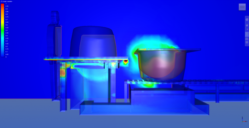
Fig. 1. CFD modeling results. Dust distribution in vertical section
Technology selection and process development
For 3D-modeling of ventilation systems and enclosing structures it was planned to use Autodesk Revit, for calculations of pollution and ventilation systems – Autodesk CFD.
The work began with the modeling of the room. All the characteristics of its geometry – columns, crossbars were taken into account. The equipment, tables and even figures of people in their real workplaces were placed in the room. Then, as a first approximation, without detailing, a local exhaust and intake ventilation system was designed. After that, the experts exported the resulting geometry to Autodesk CFD for preliminary calculations. In total, three iterations were subsequently performed on the selection of the design of ventilation systems, at each subsequent iteration, specialists took into account the CFD calculation data to provide detailed drawings of systems.

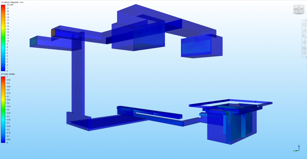
Fig. 2. Computational model of local supply and exhaust ventilation system

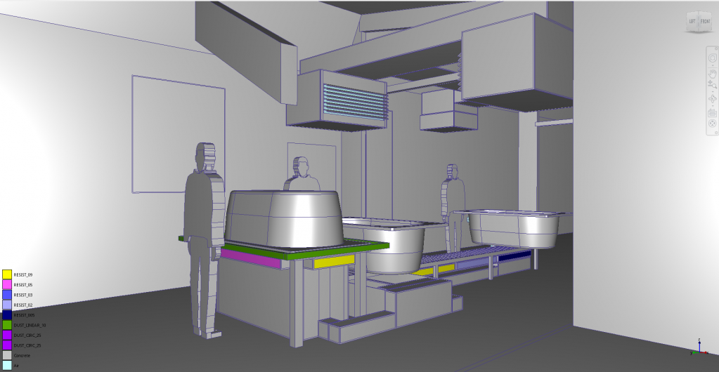
Fig. 3.3D visualization of the computational model in CFD
Flow modeling
In order to proceed to modeling, the STEP LOGIC specialists set the degree of dispersion of dust, which appears as a result of production activities in the workshop, and determined its diffusion coefficient. In the simplified 3D-model of the workshop, the dust generation points were marked, in which the limit concentrations were set. Air ducts, taking and supplying air through the floor and walls of the room, were modeled simplistically. For the exhaust system, a certain flow rate was set in the first approximation; boundary conditions were assigned to the supply grilles. Thus, basic boundary conditions were introduced into the model, which made it possible to carry out primary modeling of air flows and impose dust distribution on them. This calculation took no more than half an hour. The obtained data allowed us already at this stage to change the basic configuration of the equipment and to begin its detailed elaboration.
From simple to complex: detailing
“During the second and third iteration stages, we changed the location of the air intake devices, brought them closer to the dust extraction sites, optimized their design, and also modified the intake system to prevent high air flow velocities in the working area,” says Vadim Kalle.
The initial layout of the ventilation system configuration, taken as the baseline, has changed significantly. Some changes were made during the modeling process in Autodesk Revit. For example, it was necessary to change the location of the exhaust grilles under the conveyor because they obstructed the access to the equipment. Most of the changes were made according to the CFD calculation data. “In particular, as a result of working in CFD, we have achieved guaranteed removal of dust from the premises,” says Vadim Kalle. "The initial configuration of the inlet system provided a horizontal flow in the model. The air actually flowed through the room, and only then it entered the exhaust grilles by circular flow. We also wanted the flow to be directed directly from the large cross section supply grilles to the area where dust is released. By redistributing the exhaust grilles and changing the direction of the intake system blades, we obtained a flow which did not capture the entire room, but only the area where dust is released."
Using CFD, the optimal air flow was determined for the system in addition to the required vacuum of exhaust system, fan capacity and other parameters. The modeling helped achieve the normalized air flow rate to be provided by the ventilation system in the work space.

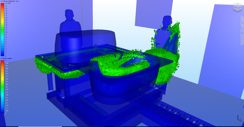
Fig. 4.CFD, 40% concentration isosurface with velocity vectors on the surface
Advantage is speed
“The calculation of the base system took only half an hour, and each calculation of the system in high detail, including 2 million elements, took 3 hours,” says Vadim Kalle. “Although the overall size of the workshop was relatively small, about 120 m2, we were dealing with a complex flow configuration, which required a high grid resolution.”
In general, we spent 2 weeks on this work. Most of this time was taken to design the system in Autodesk Revit in high detail. It was necessary to create a closed 3D geometry, a complex configuration of air ducts, static chambers with all grilles, as well as their internal volume to simulate the flow; then we had to check and eliminate collisions to ensure correct functioning of the model in CFD and to prevent intersections of geometry.
CFD tools
Vadim Kalle points out two Autodesk CFD tools that were most useful for this project. Using the first tool, Active Model Assessment Tool, the STEP LOGIC experts eliminated unnecessary detalization in the Revit model, simplified geometry before uploading it to CFD. Vadim Kalle: “We could omit the narrow edges, insignificant gaps, invisible to the eye, which did not affect the calculation, but significantly complicate it. So, in "narrow" places CFD could simulate a fine grid, which did not allow us to obtain a convergent solution. It would be necessary without any reason to increase the detalization of the project and calculate many times longer."
The second tool is Scalar Mixing, which allows its users to simulate distribution of any substance in a liquid or gaseous medium with a given concentration and diffusion rate, in this case, the distribution of dust in the air. The expert also notes the basic CFD calculation tools for finite element calculations and creation of interactive visualization of velocity and concentration distribution.
Project results
The work products are cross-sections, visualizations with distribution of velocity and dust concentration fields. A number of videos were recorded to demonstrate the workshop processes with a 3D model.
Vadim Kalle assesses the benefits of working with CFD: “In just 2 weeks, we obtained the best solutions for ventilation and decontamination. At the 3D-model stage, we conducted a test in our virtual laboratory. Without CFD modeling, an optimal ventilation system could not be implemented without 2–3 iterations. We would have to test the configuration of ready-made systems, which would have lead to a rise in the cost of the project by 200–300%."
